This document will tell you almost enough to let you build your own modem cables and track down problems caused by improper RS-232C cables. It explain true, null and drag queen cables. It will also explain in simple language a lot of the mystery of RS-232C interfaces. It explains all 25 pins of the interface and what they are for. It explains BPS/Baud rates and flow control, Stop Bits, Start Bits, parity, async and sync. I also hope to dissuade you from ever buying a serial printer.
You have my permission to reproduce and use this document for any purpose except military.
Since Ma Bell was female and since Bell Telephone were the early suppliers of modems, modems traditionally present female connectors. Because Bell employees were predominantly heterosexual they arranged that Terminals should present complementary male connectors. The modem and terminal were joined in holy matrimony by a cable with one male and one female end.
The other reason Bell chose female connectors for their modems is that male connectors are more fragile — the tiny protruding pins are likely to break off. The male connectors belonged to the customers, the robust female ones to the phone company.
I say this tongue in cheek as a memory aid.
In any RS-232C connection, one end must pretend to be the modem DCE (Data Communications Equipment) and the other the terminal DTE (Data Terminal Equipment).
RS-232C connections are common between computers and modems, computers and printers and between two computers.
Polymorphous perverse companies such as Osborne, Hewlett Packard and US Robotics, found Ma Bell’s sexual symbolism too constraining. They invented modems that presented male connectors, computers that pretended to be modems and and…
25 Pin D-shaped connectors are used, but some companies, notably Apple, sometimes use non-standard nine pin connectors. I suspect wicked motives such as cost cutting and attempting to lock you into buying their own brands of peripheral equipment.
Nearly all companies fail to implement the full standard. Only a subset of the full 25 pins are functional. This is what makes RS-232C connections such a headache. RS-232C connections are unavoidable with modems, but NEVER use serial RS-232C printers if you can possibly get parallel interfaces instead.
Male 25 pin connectors have two rows of pins numbered like this:
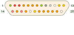
Note that because the top row has more pins, it is longer. This gives the connector its D shape. The D shape prevents ensures that you will destroy a cable if you persist on pushing it on upside down.
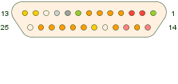
Female 25-pin connectors have two rows of pins numbered like this:
Voltages between +3 to +25 volts are considered ON, Spacing, or Binary 0.
Voltages between -25 to -3 volts are considered OFF, Marking or Binary 1, yes Virginia 1. Since the Transmit Data line idles by sending ones, it was considered reasonable to use the negative voltage (usually meaning off) to represent binary 1.
In theory RS-232C interfaces are robust enough that you can short any two pins together without smoke pouring out, but don’t count on it.
| Most Important RS-232C Pins |
|---|
| Pin Name and Function |
| TD (Transmit Data) |
| RD (Receive Data) |
| SG (Signal Ground) |
| RTS (Request To Send) |
| CTS (Clear To Send) |
| DTR (Data Terminal Ready) |
| DSR (Data Set Ready) |
| DCD (Data Carrier Detect) |
| SQ (Signal Quality) |
| RI (Ring Indicator) |
In theory you can have 4 separate conversations going on simultaneously. The primary and secondary send and primary and secondary receive. However, I have never seen the secondary used except in Mohawk equipment.
| Pin# | Interchange Circuit |
Pin Name | Purpose |
|---|---|---|---|
| 01 | AA | Protective Ground | Frame ground, usually the shield. Sometimes jumpered to signal ground. |
| 02 | BA | TD | Transmitted Data. Usually Marking — Binary 1s — while idling. Data from terminal to modem binary 0 start bit, then data for a character, then binary 1 stop bit then the sequence repeats for the next character. Note this is NOT a tri-state line. Novices often presume there will be one voltage level for 0, another for 1 and yet another for not sending data. However, there are only two voltage levels. So when the line is not sending data it sends 1s. I just lied a little, there really is a third voltage level; when all the power is off, there will be a third level — no volts, but this is not used for idling. |
| 03 | BB | RD | Received Data usually Marking — Binary 1s — while idling Data from modem to terminal |
| 04 | CD (Compact Disc) | RTS | request to Send ON means terminal wants to send data. The terminal will wait until the modem says it is ok by raising CTS. |
| 05 | CB | CTS | Clear to Send ON means modem says it is ok for the terminal to start sending. Most of the time CTS should be on. Only in old fashioned half-duplex modems is there any reason not to send at any time. With printers the RTS CTS pair can be used for flow control (handshaking). The printer can pretend to be the modem. When it is getting behind printing it drops CTS, to stop the flow of incoming data. But most printers are not content with that passive rôle and want to also pretend to be the Terminal. Then they play games with DTR or RTS hoping the other end will understand these new uses for the old pins and leave it up to you to design a cable to make the printer look like a modem. See RTR/RFS below. In the new compressing modems, flow control again becomes important. The computer sends data to the modem at very fast rate. Sometimes when compression is successful, the modem can keep up. Sometimes the compression does not squeeze much, then the modem cannot keep up and drops CTS to tell the computer to back off for a while. |
| 06 | CC | DSR | Data Set Ready ON means the modem is powered on. In the olden days modems were called Data Sets. Then IBM (International Business Machines) started calling Files Data Sets. To avoid confusion we started calling Data Sets modems. |
| 07 | AB | Signal Ground common ground for all signal lines. In the newer Rs422 system each signal gets its own private return ground. | |
| 08 | CF | DCD | Carrier Detect. The modem is receiving whistles from some remote modem. It turns this ON to let the terminal know about it. We are connected. |
| 09 | testing often +12 volts but don’t count on it. | ||
| 10 | testing often -12 volts but don’t count on it. | ||
| 11 | unused | ||
| 12 | SCF | secondary Carrier Detect | |
| 13 | SCB | secondary Clear To Send | |
| 14 | SBA | secondary Transmitted Data | |
| 15 | DB | TC | Transmit Clock supplied by MODEM DCE square wave signal so terminal knows when to start sending the next bit of transmitted data. (not used in Async transmission). |
| 16 | SBB | secondary Received Data | |
| 17 | DB | RC | Receive Clock supplied by MODEM DCE square wave signal so terminal knows when to sample each bit of received data (not used in Async transmission) |
| 18 | unassigned | ||
| 19 | SCA (Secondary Request to Send) | secondary request to send | |
| 20 | CD | DTR | Data Terminal Ready. Terminal is powered on. Terminal drops this signal to persuade the modem to hang up the phone. |
| 21 | CG | SQ | Signal Quality. The modem turns this on to tell the terminal it likes the quality of the carrier coming in. It turns it off if it suspects errors due to static. Rarely supported. |
| 22 | CE | RI | Ring Indicator. The modem turns this on each time an incoming call rings the phone. The terminal would turn on DTR to tell the modem it is ok to answer. |
| 23 | CH/CI | Speed Indicator. This is a two way wire. For outgoing calls the terminal turns this ON to tell the modem to use higher speed e.g. 1200 verses 300 BPS (Bits Per Second). For incoming calls the modem tells the terminal data is coming at higher speed by setting it ON. | |
| 24 | DA | (TC) | Transmit Clock provided by the terminal. Not used in Async communications. For sync communications it is usually the duty of the modem to provide the clock. In Async communications the modem doesn’t care about the clock. It doesn’t need one. So this pin is only useful in the rare situation the terminal is providing the clock to the modem in synchronous situations — e.g. in back to back X.25 between two computers. |
| 25 | unassigned. |
A normal modem cable run straight through with pin 1 male and the end that hooks onto the modem presents a male end to the modem’s female. Sometimes the sex of connectors can get confused and you will need non standard sexed ends on your cable.
Nearly always one end of the connection will support a different subset of the pins from the other. For example, the modem may be watching RTS but the terminal doesn’t support it. In that case you have to fake it by strapping the RTS pin permanently ON by connecting it to the +12V test pin, or by strapping it to some other signal such as DTR that the terminal does support.
The pins you have trouble with most often are 4, 5, 8 and 20.
You can find out which lines are being supported by perusing documentation or by using a $200 breakout box. A breakout box is a set of 25 LEDs (Light-Emitting Diodes). I use a Microplex M112 model that is well designed for async work. Fancy versions use Red/Green/Yellow to indicate line state. They also come with a set of switches and little jumper wires so that you can build experimental cables instantly. You can also see if signals are in spec. Sometimes the signals that are nominally +5 volts droop down in the 2.5 volt range, which is no-man’s land. Ordinary LED (Light-Emitting Diode) tests will not show up the trouble. Once you find the magic combination you can get a permanent cable built for about $30.
You can also buy a little connector with do-it yourself jumpers with no lights for under $20.
Sometimes you wish to connect two computers or a computer and a printer together. One of them has to pretend to be a modem (DCE ) and one has to pretend to be a terminal (DTE ). Sometimes equipment is flexible and sometimes they refuse to go in drag. When you have two pieces of equipment both steadfastly insisting on being terminals ( DTE) or two pieces both steadfastly insisting on being modems (DCE ), what do you do?
For two steadfast terminals, (the most common case) you build a special null modem cable that logically looks like two modems back to back over a very short phone line.
A typical null modem cable looks like this:
| From Pin Name |
From Pin Number |
To Pin Number |
To Pin Name |
|---|---|---|---|
| Frame | 01 | 01 | Frame |
| TD | 02 | 03 | RD |
| RD | 03 | 02 | TD |
| RTS | 04 | 05 | CTS |
| CTS | 05 | 04 | RTS |
| DSR | 06* | 06* | DSR |
| ground | 07 | 07 | ground |
| CD | 08* | 20 | DTR |
| TC | 15* | 15* | TC |
| RC | 17* | 24 | (TC) |
| DTR | 20 | 08* | DCD |
| SQ | 21* | 21* | SQ |
| (TC) | 24 | 17* | RC |
This is a reasonably classy version of the null modem cable. You can often get by without connecting pins 15 17 and 24 at all.
Sometimes you also have to jumper 6 and 21 together on each end as well.
A null modem cables between two computers DTEs (Data Terminal Equipments) would normally have two female ends. A null modem cable to go between two DCE devices would normally have two male ends.
Hewlett Packard makes printers with female connectors that at first glance appear to be DCE. However, at heart they are DTE (males). What you need is a null modem cable with a male end for the printer and a female end for the computer. I have coined the mildly pejorative term drag queen cable to describe these. Others may call them Hewlett Packard Printer Cables. Beware the drag queen cable. You cannot tell it apart from a standard true modem cable unless you have labeled it. You have to get out a voltmeter and measure the resistance to see which pins are attached to which to tell them apart.
| Pin# | Pin Name |
|---|---|
| 02 | TD |
| 03 | RD |
| 04 | RTS |
| 05 | CTS |
| 06 | DSR |
| 07 | SG |
| 08 | DCD |
| 20 | DTR |
| 22 | Ring |
 |
 |
| Male | Female |
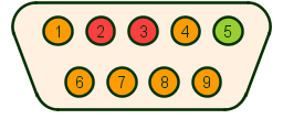
Motherboards now have USB (Universal Serial Bus) ports but some still have a 9 pin serial port or two. They typically present this male pinout.
| Pin# | Name | Purpose |
|---|---|---|
| 01 | DCD | Data Carrier Detect |
| 02 | RD | Receive Data |
| 03 | TD | Transmit Data |
| 04 | DTR | Data Terminal Ready |
| 05 | SG | Signal Ground |
| 06 | DSR | Data Set Ready |
| 07 | RTS | Request to Send |
| 08 | CTS | Clear to Send |
| 09 | RI | Ring Indicator |
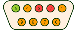
Originally DB-9 connectors were extremely non-standard. Now they seem to have settled on the pattern above. Here is one of the older patterns.
| Pin# | Pin Name |
|---|---|
| 01 | DCD |
| 02 | TD |
| 03 | RD |
| 04 | DTR |
| 05 | SG |
| 06 | DSR |
| 07 | RTS |
| 08 | CTS |
| 09 | RI |
Hayes presents a DB 25 female connector.
| Pin# | Pin Name |
|---|---|
| 01 | Protective Gnd |
| 02 | TD |
| 03 | RD |
| 05 | CTS |
| 06 | DSR |
| 07 | SG |
| 08 | DCD |
| 12 | High Speed |
| 20 | DTR |
| 22 | RI |
Apple Mac presents a DB 9 female connector.
| Pin# | Pin Name |
|---|---|
| 1 | SG |
| 2 | +5v |
| 3 | SG |
| 4 | TD +ve |
| 5 | TD-ve |
| 6 | +12v |
| 7 | CTS or transmit clock depending on mode |
| 8 | RD +ve ground this line to emulate RS-232C |
| 9 | RD-ve |
Digital Equipment Corp have many versions of RS-232C. The H8571-B is a 9-pin version that uses female D connectors. This acts something like a null modem cable, but since RTS/CTS are not supported you must use XON/XOFF flow control. Your best bet with DEC printer is to buy the optional parallel interface.
| Pin# | Pin Name |
|---|---|
| 1 | no connection |
| 2 | RD |
| 3 | TD |
| 4 | no connection |
| 5 | DSR |
| 6 | DTR |
| 7 | SG |
| 8 | no connection |
| 9 | no connection |
DEC ’s other connector is a 6-pin version that uses RJ-45 connectors (beefed up versions of the modular phone jack). Note that since RTS/CTS are not supported, you cannot cook up a null modem cable. You must use XON/XOFF flow control.
| Pin# | Colour | Pin Name |
|---|---|---|
| 1 | white | DTR |
| 2 | green | TD |
| 3 | red | TD return (ground) |
| 4 | orange | RD return (ground) |
| 5 | black | RD |
| 6 | blue | DSR |
Why you should not buy a serial printer.
Serial printers have one saving grace. They can be attached to your computer with a cable up to 50 feet long. Parallel printers should be attached with as short a cable as possible (6 to 15 feet).
If you have a distance problem it is better solved using a parallel interface with:
You transmit the bits of a character over a serial link at a fixed rate measured in Bits per Second. 300 BPS is also erroneously called 300 Baud. A few years ago, everyone used the terms as if they were synonymous. But now people are more careful to use the proper term.
What is the difference? When a modem transmits information to another it sings to the other modem. It changes the sound many times a second. The number of times a second it changes the sound is the Baud rate. Since each sound might encode information via loudness, pitch and/or phase. Further, since each sound might be made up of chords of several tones, each burst of sound may encode many bits of data. In old fashioned FSK (Frequency Shift Keying) 300 BPS modems, the encoding was very simple — one of two tones. In those modems the Baud rate and the BPS rate were the same. In modern modems, the Baud rate might be around 40 while the BPS rate is around 56,000.
Modems used to run at 300 BPS, 1200 BPS or 2400 BPS. Now adays most modems run at 28,000 BPS, 33,000 BPS or 56,000 BPS. Over dial up lines, even the fanciest modems have trouble getting above 26,000 BPS for long distance, though most expensive modems give the illusion of higher speed by compressing on the fly.
The general rule about selecting BPS rates is to make both ends of the connection run at the same rate and make them both as fast as possible. Usually you only have a few choices. However, if that does not work, pick 300 BPS for both ends and see if it works. Then gradually increase the speed backing off when you get too fast for reliable operation.
Modern modems will usually successfully negotiate the fastest possible speed they can both handle. If you have simply a null modem cable, without modems, then it is up to you to set this. You can do that by:
Flow control problems are not as severe at slow speeds. Even if you choose the wrong flow control protocol, (or if both ends insist on using different flow control protocols) things may still work if you run slowly enough.
When one sends data faster than the other end can receive it, there are several protocols for the receiver to request the sender to slow down.
When the RTS pin is used as a DTE to DCE flow control mechanism, it is properly called RTR (Ready To Receive) (Ready To Receive). The CTS signal has been renamed RFS (Ready For Sending) (Ready For Sending).
A third common protocol is called Enq/Ack used primarily by Hewlett Packard equipment.
Modems idle by sending ones. How then could a modem send a character of all ones? It would look just like more idling. The way the modems solve the problem is by preceding each character with a single 0 bit. The transition from 1 (mark) to 0 (space) signifies the start of a character. That transition also synchronizes a clock in the receiver so that it can then sample the succeeding bits exactly in the middle.
How the could a modem send a long string of zero characters? It would look like a smooth unbroken stream of space. How could the modem tell 999 successive zero characters from 1000? The solution is to append a 1 (marking bit) to the end of each character. This way in each character there is guaranteed to be a TRANSITION as the start bit drops back from 1 to 0.
In older equipment you needed 1.5 or 2 stop bits. The stop bit had a secondary function of providing delay for the mechanical parts of a Teletype to get ready for the next character. In modern communications 1 stop bit is ample. Sometimes you will even see 0.5 or 1.5 stop bits. However, you must configure both sender AND receiver to expect the same number of stop bits.
Modems often use a crude error detecting mechanism by adding an extra bit to each character sent, so that the number of ones is always even. If static reverses one of the bits, the result will no longer have an even number of ones in it and the receiving end will know something has gone wrong.
There are several possible parity schemes, the most common near the top:
| N | None | Add no parity bit. |
| E | Even | Add a 1 or a 0, to fudge it so that the number of 1s in total is even. |
| M | Mark | Add a useless parity bit that is always 1. |
| O | Odd | Add a 1 or a 0, to fudge it so that the number of 1s * in total is odd. |
| S | Space | Add a useless parity bit that is always a 0. |
When devices communicate via RS-232C they have to decide on how big an alphabet they need. For example if an alphabet of only 32 characters were sufficient, then only 5 bits per character are needed. 32 is 2*2*2*2*2. With five possible bits, each being either 0 or 1, there are 32 possible combinations. Each combination can be assigned to one of the letters of the alphabet. A simple 5 bit code is called Baudot after the man who invented the Teletype. It has only upper case and a special figures and letters code to let you know when to interpret the letters as numbers and vice versa.
Most bulletin boards need an alphabet of 128 characters to communicate. Thus they need a 7 level code. This ASCII (American Standard Code for Information Interchange) code contains both upper and lower case and punctuation. IBM PCS use an 8 level code giving them a 256 character alphabet. It adds accented characters and a line drawing set with both single and double lines.
A UART is a chip inside your computer that converts between the 8-bits per byte parallel format used internally to the one-after-another strings of bits (marks and spaces) used by the world of modems. UART stands for Universal Asynchronous Receiver Transmitter. Modern day UARTs do more that just act as UART s, so properly they should be given the more grandiose name ACE (Asynchronous Communications Element) — Asynchronous Communications Element. The problem is, if you call them ACE s only a few of the cognoscenti will know what you are talking about.
There are two types of UART in common use — the 16450 and the 16550. The newer 16550 chip has a buffer to store 16 characters. Programs like DESQview and Windows often keep the CPU (Central Processing Unit) so busy with other tasks, it doesn’t manage to service the UART before the next character arrives. When that happens, the incoming character is lost. The buffer provides a safety net, since the CPU only has to empty the UART 1/16 as often.
By analogy, the 16550 is like buying an enormous trashcan for your kitchen. Even if you fail to empty it regularly, it still won’t overflow.
I wrote a little utility called UART that will tell you which kind of UART you have on each serial port. It can detect the old 8250 used in XTs, the 16450, the early defective 16550s that did not buffer, the buffered 16550AF and the new PS/2 DMA (Direct Memory Access) UART.
If you were to watch the TD (Transmit Data) wire going from your computer to an ordinary async modem, here is what you would see. For each character, first the UART sends the start bit, always a 0. The transition from the idling mark to space at the beginning of the start bit synchronizes the clocks of the sender and receiver.
Then the UART sends 7 bits of the character itself starting with the least significant (rightmost) bit. Yes, you read that correctly. It works backwards from right to left.
Then comes the optional parity bit. When you have even parity, the parity bit is just a finagle bit to ensure there are an even number of 1s all told in the character. If the receiver counts an odd number of 1s, it knows the transmission must have been garbled. Unfortunately, if two bits were garbled, the parity might still look ok.
Finally comes the stop bit, always a 1. Its function is just to get us back to marking state again so that we can notice the transition to space for the start bit of the next character. Then the whole process repeats for the next character. The UART may send a long string of uninterrupted 0s. Since the start bits are missing, this cannot be interpreted as data, but as a BREAK — a request to stop.
If you were to snoop on the TD (Transmit Data) wire between an old IBM 3270 CRT (Cathode Ray Tube) or a 3870 remote workstation and an IBM mainframe using the old Binary Synchronous protocol, here is what you would see.
There are no start and stop bits on each character. Instead you will see bursts of data characters going by with no idle time between them. Each character has a full 8 bits. At the head of the message burst are a group of SYN characters (hex 16). In binary they look like 0010110. Even in a long string of them.
What syn chars look like going by on an oscilloscope
 001011000101100010110
   _ __   _ __   _ __
 __ _  ___ _  ___ _  _
it is easy for a UART to unambiguously determine where the SYN character starts. These SYN characters help the receiver to precisely synchronize its clock with the sender. The clock tells the receiver when to sample the data stream. The data stream is not neatly divided into bits they way the diagrams might lead you to believe, it is just a voltage on a wire that wanders up and down. It is up to the receiver to figure out when to best sample the voltage to extract each bit. From here on, any refinements in the synchronization must be done by looking at data only — which may or may not have transitions. In very long messages, sometimes we throw in a few sync characters in the middle of a message to help resynchronize.
As you might guess, timing has to be more accurate for synchronous transmissions than for async. In a message of 200 characters of 8 bits each, we would want it accurate to one part in 25,600 i.e. 1/16 of a bit time.
There is no parity bit on each character. Instead some characters are appended to the message called the CRC (Cyclic Redundancy Check) (Cyclic Redundancy Check) that act something like a parity bit.
The overhead of the CRC is substantially less than the bit-per-character parity bit used in async and quite a bit more powerful at detecting errors. Imagine treating the message as a giant binary number and dividing by prime number like 149. The remainder would be a number between 0 and 148. If you tacked that number on the tail end of the message, the receiver could do the same calculation. If he got the same number, changes are all the bits got through intact. If he got a different number, something must have been garbled.
Because division is so time consuming for computers, they do a different kind called polynomial division over the ring of integers 0 and 1. It is much like regular division, except you do an XOR (exclusive OR) where in regular long division you subtract.
The advantage of synchronous transmissions are:
The disadvantages are:
Most modern async modems transparently revert to synchronous when talking to other clever modems, e.g. MNP-4 and MNP-5, V.90. You can notice them doing this when data comes at you in bursts. The modems are breaking up the continuous stream into discrete messages and automatically retransmit on error.
The HDLC (High-level Data Link Control) protocol used when you attach to an X.25 packet net resolves some of the problems of the older bisync protocol. In Bisync, you can in theory have long stretches without any transitions. HDLC fixes that by ensuring there is a transition at least every 5-bit times. This help keep the clocks in sync. Bisync reserved some of the characters to control the line e.g. SYN. This meant, if the corresponding bit patterns occurred accidentally in the data, special quoting measures had to be taken to ensure they were not mistaken for control characters. HDLC has no such troubles since it has a special flag to mark the ends of messages. The flag violates the transitions-every-5-bits rule. It cannot possibly be confused with data. This means HDLC is transparent. All possible bit patterns can be sent without special handling.
Each message begins and ends with some flags to help synchronization. The data are sent with extra bits inserted after strings of 5 zero bits or 5 one bits, to force a transition. There is no need to insert SYN characters in the middle of the message.
If someone says, I have a 2400-N-8-1 setup, he means I am running at 2400 BPS, am using No parity, 8 data bits and 1 stop bit. If he says I have a 300-E-7-2 setup he means I am running at 300 BPS, using Even parity, 7 data bits and 2 stop bits.
The crucial thing is that parties communicating must be set up with exactly the same parameters. If one is talking at 300 BPS and the other is listening at 2400 BPS, nothing (usually) is going to get through. Some of today’s smarter devices take your settings with a grain of salt, just as hints to get started. They automatically adjust depending on what the other party is doing. However, most problems with RS-232C can be traced simply to failing to match these four parameters on both ends.
This page is posted |
http://mindprod.com/jgloss/rs232c.html | |
Optional Replicator mirror
|
J:\mindprod\jgloss\rs232c.html | |
Please read the feedback from other visitors,
or send your own feedback about the site. Contact Roedy. Please feel free to link to this page without explicit permission. | ||
| Canadian
Mind
Products
IP:[65.110.21.43] Your face IP:[216.73.217.43] |
| |
| Feedback |
You are visitor number | |